Connecting the RC to the Nano
Now comes the part that should differ the most, based on the RC you got. But don't worry, it's very much doable no matter the RC you got!
Finding your ESC/Servo
The first thing you should do is find your ESC and your Servo connectors, which should be a three wire connector coming from your RC car.
If you've bought a car that came with a wireless receiver, both the connectors should be connected to it. Here's what it looked like on my RC:
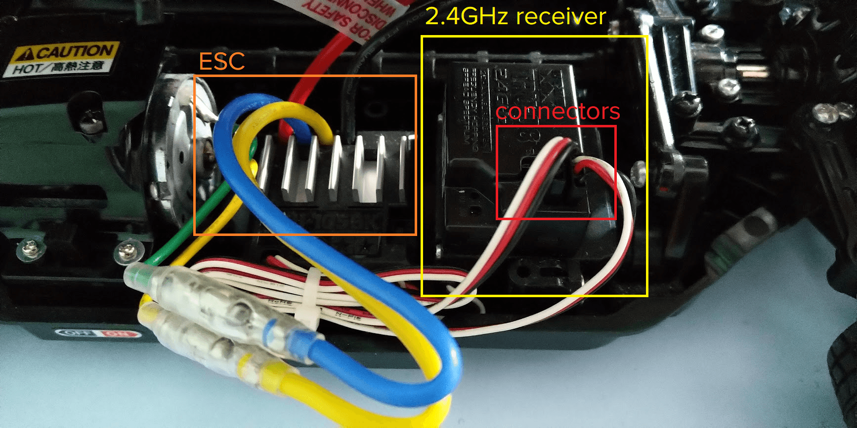
If you didn't have a wireless receiver, you should be able to see a connector coming out of your ESC, which is hooked to the RC motor, and a connector coming out of your steering servo, found at the front of your RC.
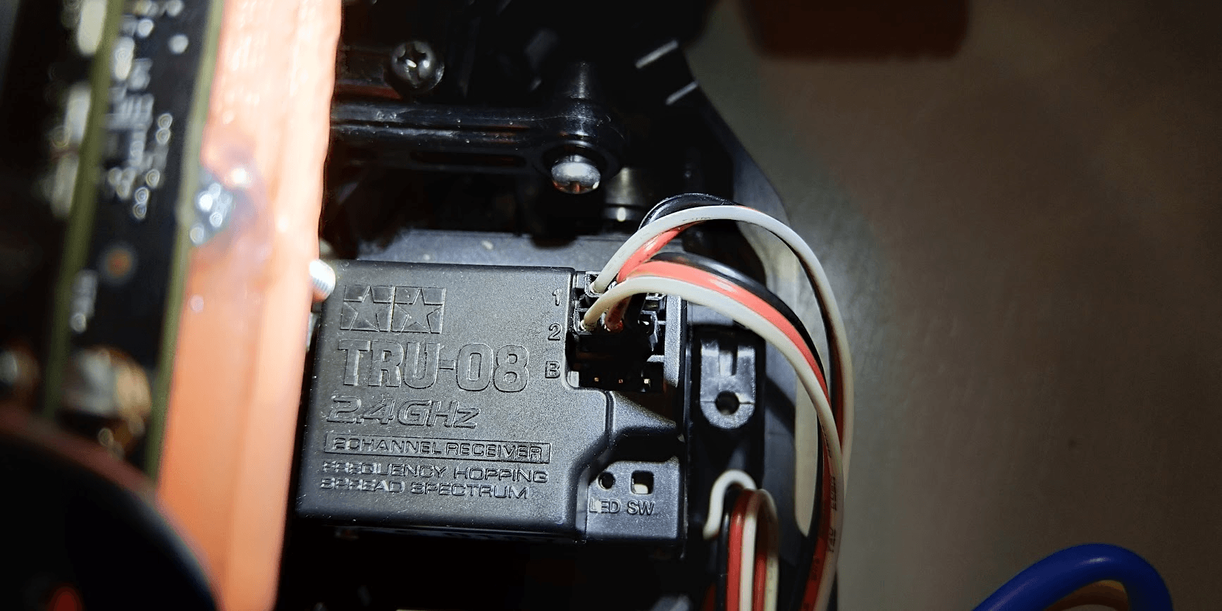
Here's a closeup of the two connectors connected to the receiver, with the first channel being the steering servo and the second one being the ESC, in my case:
Okay, we found the connectors, how do we hook them up to our car?
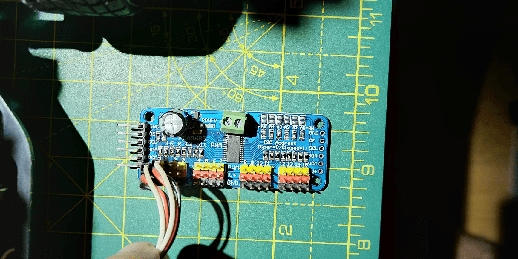
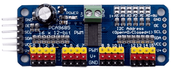
Enter: the PCA9685
We connect them to the first two channels (0 and 1) of our PCA9685, highlighted in green and blue:
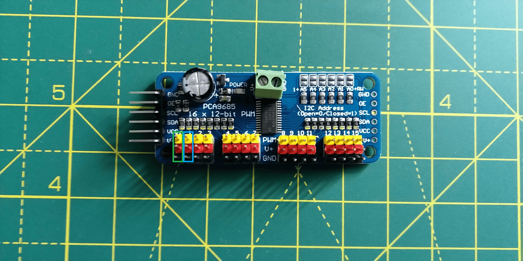
It doesn't matter which channel you connect the servo to, and which one the ESC to, just take note which one went where, you'll need it later on. You can see the numbers denoting the channels above the three pins. I've connected mine to the zeroth and first channel:
Okay, so we hooked up our car to the PCA9685. Now we need to hook it up to our Nano to be able to control the car through it.
But first, let's talk a bit about the way the Nano communicates with the RC through the PCA9685, using a protocol called I²C (Inter-Integrated Circuit) (pronounced: I-squared-C).
Feel free to skip this part if you aren't interested in the alternatives to I²C and why we're using it. You don't need to understand this stuff in order to continue with the tutorial. That being said, it wouldn't hurt to get to know a few other protocols, just to know what's out there and how they differ.
CLICK HERE TO SKIP
I2C
What the heck is I²C?
It was designed back in the ‘80s by Philips, to enable components on a circuit board easily communicate with each other. So it's a protocol components use to talk to each other.
If you want to read a bit more, here's the specification by NXP, since Phillips semiconductors migrated to NXP back in 2006.
There's also a pretty neat primer you can read on the i2c-bus.org site.
Why I2C? Alternatives?
This is basically a TL;DR of the awesome SparkFun I²C tutorial, be sure to check it out if you wanna go into more depth. I'll assume you have some basics of UART and SPI while going through them.
If you are interested in this kinda stuff, but haven't really done any embedded/electronics work before, please do check out the Engineering Essentials tutorials on SparkFun, they're great.
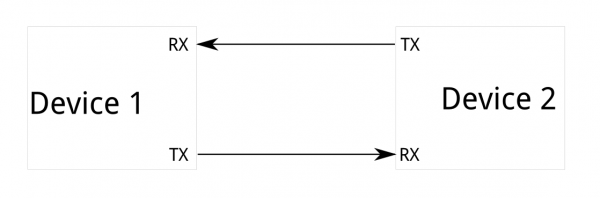
Serial UART:
- Serial ports are asynchronous (no CLK), so both devices have to agree on a data rate ahead of time: any excessive clock difference will result in garbled data.
- Requires hardware overhead: the UART at either end is relatively complex and difficult to accurately implement in software if necessary. At least one start and stop bit is a part of each frame of data, meaning that 10 bits of transmission time are required for each 8 bits of data sent, which eats into the data rate.
- Two, and only two devices: bus contention (where two devices attempt to drive the same line at the same time) is always an issue and must be dealt with carefully to prevent damage to the devices in question, usually through external hardware.
- Data rate - only a fixed number of baud rates available, highest of which is usually 230400 bits per second.
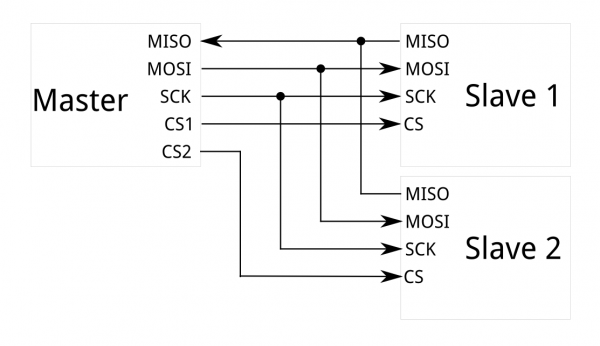
SPI:
- Number of pins needed: four lines for a single master -> slave connection and each additional slave needs another chip select I/O pin on the master.
- A larger number of devices rapidly proliferates the connections - routing signals sucks, sometimes impossible in tight PCB situations.
- It's pretty good for high data rate full-duplex connections (10MHz - bits), scales nicely.
- The hardware is pretty simple - a shift register, easy software implementation.
I2C
- I2C requires a mere two wires, like asynchronous serial, but those two wires can support up to 1008 slave devices.
- Unlike SPI, I2C can support a multi-master system, allowing more than one master to communicate with all devices on the bus (although the master devices can't talk to each other over the bus and must take turns using the bus lines).
- Data rates fall between asynchronous serial and SPI; most I2C devices can communicate at 100kHz or 400kHz. There is some overhead with I2C; for every 8 bits of data to be sent, one extra bit of meta data (the “ACK/NACK” bit) must be transmitted.
- The hardware required to implement I2C is more complex than SPI, but less than asynchronous serial. It can be fairly trivially implemented in software.
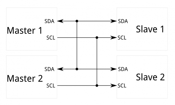
I2C Signal basics
Each I2C bus consists of two signals: SCL and SDA.
- SCL is the clock signal, and SDA is the data signal.
- The clock signal is always generated by the current bus master; some slave devices may force the clock low at times to delay the master sending more data (or to require more time to prepare data before the master attempts to clock it out). This is called “clock stretching”.
PWM basics
PWM is a digital (i.e. square wave) signal that oscillates according to a given frequency and duty cycle.
- The frequency (expressed in Hz) describes how often the output pulse repeats.
- The period is the time each cycle takes and is the inverse of frequency.
- The duty cycle (expressed as a percentage) describes the width of the pulse within that frequency window.

You can adjust the duty cycle to increase or decrease the average “on” time of the signal. The following diagram shows pulse trains at 0%, 25%, and 100% duty:

Note: Most PWM hardware has to toggle at least once per cycle, so even duty values of 0% and 100% will have a small transition at the beginning of each cycle.
Example: LED Brightness
- 20% duty cycle at 100 Hz or above will just look dimmer than fully on.

PCA9865 overview
-
Adjustable frequency PWM up to about 1.6 KHz.
-
12-bit resolution for each output: for servos, that means about 4us resolution at 60Hz update rate, 4096 levels.
-
Multiple Drivers (up to 62) can be chained to control still more servos. With headers at both ends of the board, the wiring is as simple as connecting a 6-pin parallel cable from one board to the next.

-
Board 0: Address = 0x40 Offset = binary 00000 (no jumpers required)
-
Board 1: Address = 0x41 Offset = binary 00001 (bridge A0)
-
Board 2: Address = 0x42 Offset = binary 00010 (bridge A1)
-
Board 3: Address = 0x43 Offset = binary 00011 (bridge A0 & A1)
-
Board 4: Address = 0x44 Offset = binary 00100 (bridge A2)
-
Board 5: …

PWM Controlled Servo basics
- PWM signals go into the signal demodulation circuit through the receiving channel, so to generate a DC bias voltage.
- It will then be compared with the voltage of the potentiometer, and thus a voltage gap is obtained and input into the motor driver IC to drive the motors to rotate clockwise or anticlockwise.
- When the speed reaches to a certain number, it will drive the potentiometer R to rotate by the cascaded reduction gear, until the gap is reduced to 0 and the servo stops spinning.
- A servo is controlled by PWM signals, and the change of duty cycle control that of the position the servo rotates to.
A typical servo motor expects to be updated every 20 ms with a pulse between 1 ms and 2 ms, or in other words, between a 5 and 10% duty cycle on a 50 Hz waveform.
The period of 20 ms (50 Hz) comes from the days where the signal was encoded in PPM format to be sent over the air.
The PPM period was around 22.5 ms, and the conversion to PWM was trivial: the time of the PWM high state was the time position of the PPM pulse for that servo.
RC Servo basics
-
Modern RC servo position is not defined by the PWM duty cycle (ON/OFF time) but only by the width of the pulse.
-
The frequency doesn't matter as long as it is between 40 Hz and 200 Hz.
-
Typically expects around 4.8V to 6V input on the power wire (varies by car) and a PWM control signal on the signal wire.
-
Three wires are colored black-red-white, or brown-red-yellow, where the dark wire (black/brown) is ground, and the center wire (red) is power, and the light wire (white/yellow) is control.
-
RC-style PWM:
- One pulse is sent 60 times a second, and the width of this pulse controls how left/right the servo turns.
- 1500 microseconds - the servo is centered;
- 1000 microseconds - the servo is turned all the way left (or right);
- 2000 microseconds - the servo is turned all the way in the other direction

RC ESC basics
- Pulse between 1000 and 2000 microseconds
- Controls the power to the motor so the motor spins with different amounts of power in forward or reverse.
- Again, 1500 microseconds typically means “center” which for the motor means “dead stop.”
My schematic:
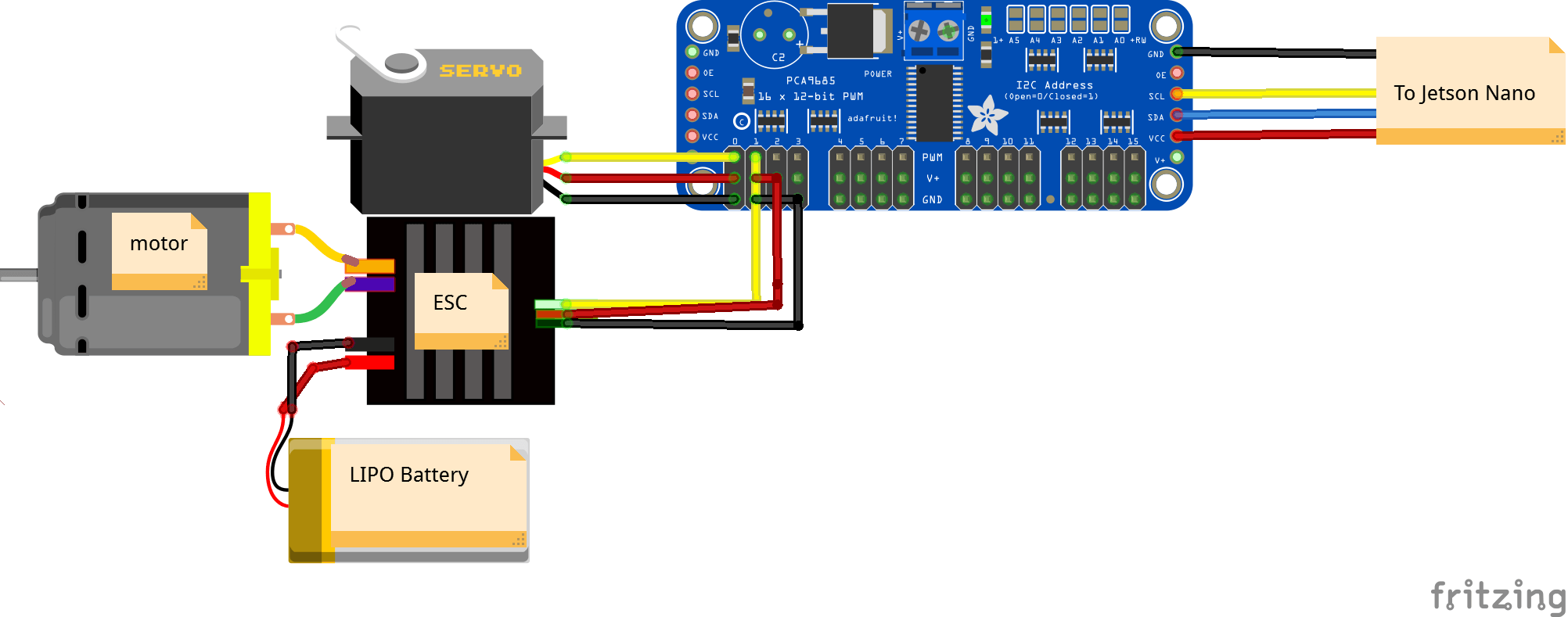
Note to self: It is not a good idea to use the Jetson 5V pin to power your PCA9865. Electrical noise and ‘brownouts’ from excess current draw can cause the Nano to act erratically, reset and/or overheat. The PCA9685 should get its own, separate power supply.
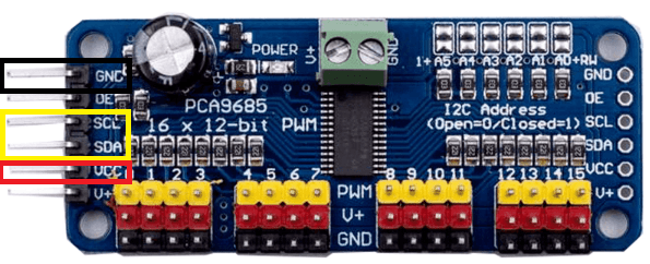
Connecting the PCA9865 to the Nano
We'll be using the SCL, SDA I2C pins from the PCA9865, along with the GND and VCC pins for power:
To connect them to the Nano, we first have to find out which of the Nano pins on its J41 header we should use. Luckily, the Jetson Nano J41 header has the same pinout as the Raspberry Pi, which you can see here, or just use the TL;DR below:
- 3V3: labeled red, position 1 and 17, connect PCA VCC pin to either of them
- GND: labeled black, all over the place, connect PCA GND pin to any of them
- I2C busses: labeled yellow, there are two of them:
- Bus 0: position 27 (SDA) and position 28 (SCL)
- Bus 1: position 3 (SDA) and position 5 (SCL)
- Connect the PCA SDA and SCL pins to either bus
- Note: the SDA/SCL pins come in pairs, you have to choose a pair/bus which you'll use
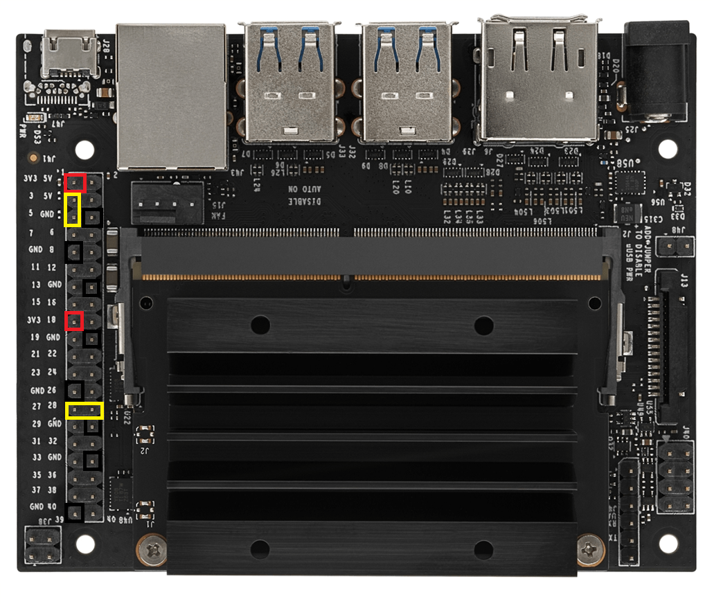
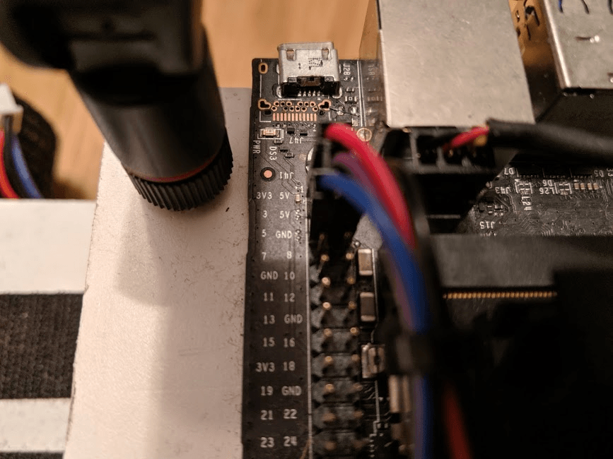
I've connected mine to the first bus (Bus 0):
- PCA -> Nano:
- 3V3 -> 1
- SDA -> 3
- SCL -> 5
- GND -> 6