Camera calibration: Explaining camera distortions
Since we're using only cameras to obtain the entirety of data we'll use to drive our car around the real world, we're sure trusting them a lot. We're trusting that they'll provide us with accurate representations of real world 3D objects as 2D images we'll feed into our neural network.
But we shouldn't take that for granted. Cameras, albeit cheap and easy to use, come with all sorts of issues when it comes to mapping the 3D world onto a 2D sensor/image correctly. But luckily, we can do something about it.
The pinhole camera model
The pinhole camera model is a model of an ideal camera, that describes the mathematical relationship between the real world 3D object's coordinates and its 2D projection on the image plane. 1

Pinhole cameras were the very beginning of photography 2, and are used even today to explain basic photography to students.
They posses some advantages over our regular lens cameras:
- They have near infinite depth of field; everything appears in focus.
- No lenses are used to focus light, so they have no lens distortion and wide-images remain absolutely rectilinear.
Basically, the smaller the pinhole gets, the more the resolution increases, until we reach the diffraction limit, at which point the image just gets darker and blurrier. Also, the smaller the pinhole, less light comes in, so the exposure time needs to be increased. Which brings us to the big issue with them:
- Their exposure times are really long, which causes significant motion blur around any moving objects or it causes their complete absence if they've moved too fast.
How can we get a small pinhole that gets a lot of light? We can use a convex lens, for starters.
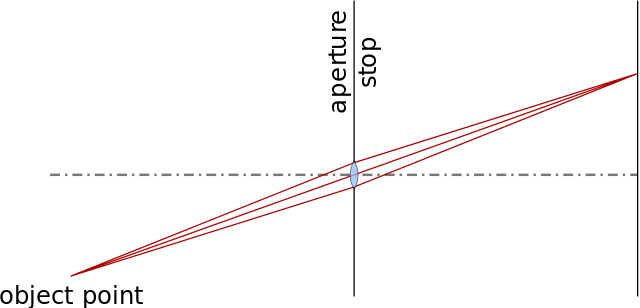
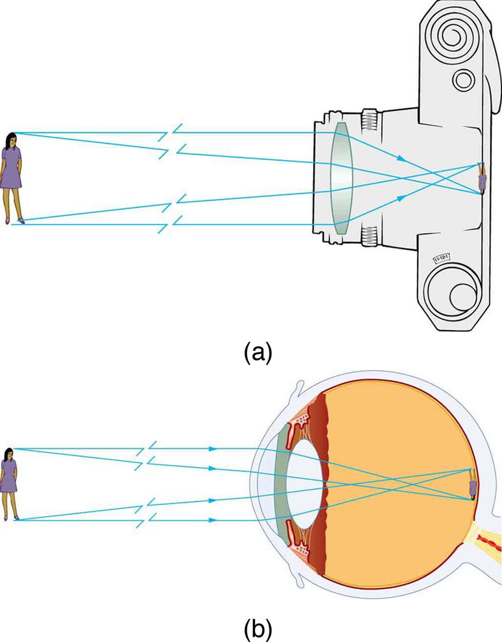
Why does this help: instead of a single ray of light illuminating a single image point, now pencils of light illuminate each image point. Even our eyes use lenses. :)
But of course, lenses bring the issues we've mentioned earlier:
- They have finite aperture so blurring of unfocused objects appears.
- They contain geometric distortions due to lenses, which increase as we get closer to the edges of the lenses.
Types of distortions
The first, and most common type of camera lens distortion is called radial distortion.
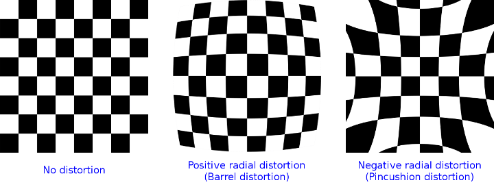
There are two types of this distortion, the positive or barrel radial distortion, and the negative or pincushion radial distortion.
In the context of self driving RCs, you'll most probably be dealing with the barrel distortion, that will most probably be caused by fisheye lenses, since we'd like to get as big a field of view as we can. Some action cams even have a FOV of 170 to 180 degrees, which causes a lot of positive radial distortion.
The other type of distortion you can come across is called tangential distortion, which occurs when the lens is not aligned perfectly parallel to the imaging plane (the sensor). It causes the image to look tilted, which is obviously bad for us since some objects look further away than they really are.
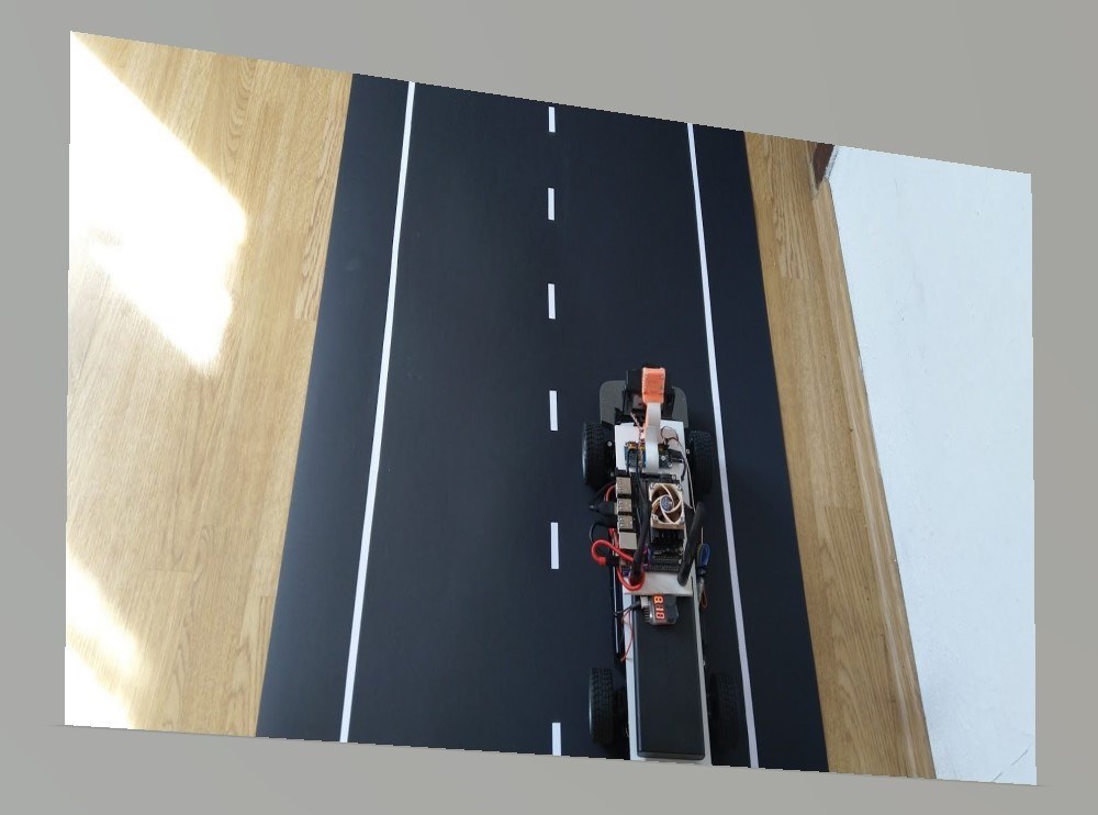
That being said, we have to expect that no camera is actually really perfect. Most, if not all have some amount of radial and tangential distortion, since the lenses are imperfect in real life, and the lens isn't always perfectly in line with the imaging plane.
Getting rid of distortions with OpenCV
Luckily for us, the radial and tangential distortions can be described using a couple of coefficients:
- $k_n$ coefficients will describe radial distortion
- $p_n$ coefficients will describe tangential distortion
The worse the distortion, the more coefficients we need to accurately describe it.
OpenCV works with up to six ($k_1$, $k_2$, $k_3$, $k_4$, $k_5$ and $k_6$) radial distortion coefficients, which should be more than enough for us, and with two ($p_1$, $p_2$) tangential distortion coefficients.
If we have the barrel radial distortion type, $k_1$ will typically be larger than zero. If we have the pincushion distortion, $k_1$ will typically be smaller than zero.
- $(X, Y, Z)$ are the coordinates of a 3D point we're imaging
- $(u,v)$ are the 2D coordinates of the projection point in pixels
- The first matrix after the equation is the camera matrix, containing intrinsic camera parameters
- $(c_x, c_y)$ defines the principle point which is usually the center of the image
- $f_x$ and $f_y$ are the focal lengths expressed in pixel units
- The matrix containing the $r_{mn}$ parameters is the joint rotation-translation matrix, a matrix of extrinsic parameters which describes camera motion around a static scene. It's used to translate the 3D coordinates to a 2D coordinate system, fixed with respect to the camera.
Since we're imaging 2D images, we'd like to map the 3D coordinates to a coordinate system:
Also, since we're not using a pinhole camera, we need to add the distortion coefficients to our model:
Since we're primarily interested in efficiently removing the radial distortion, we'll be using Fitzgibbon's division model as opposed to Brown-Conrady's even-order polynomial model, since it requires fewer terms in cases of severe distortion. It is also a bit easier to work with, since inverting the single parameter division model requires solving a one degree less polynomial than inverting the single-parameter polynomial model. 3
Finding the camera's intrinsic and extrinsic parameters
Now that we've laid out all of the formulas we use to correct radial and tangential distortion, the only question that remains is how do we get the intrinsic and extrinsic parameters.
For those purposes, we'll be using the OpenCV calibrateCamera function, along with its findChessboardCorners function.
The calibrateCamera function is based on Zhang's A Flexible New Technique for Camera Calibration and Caltech's Camera Calibration Toolbox.
It needs the coordinates of a 3D object we're imaging and its corresponding 2D projected coordinates in order to detect the intrinsic and extrinsic parameters of the camera we're using to image the object.
To easily get those coordinates, we'll be using a chessboard. A chessboard is an object with a known geometry to us and it has easily detectable feature points. Such objects are called calibration rigs or patterns, and OpenCV has a built-in function that uses a chessboard as a calibration rig, the findChessboardCorners function.
The findChessboardCorners function attempts to determine whether the input image is a view of the chessboard pattern and automatically locate the internal chessboard corners.
The cool thing with this is that we can print out a 3D object (a chessboard) whose geometry is well known to us, and map its 3D coordinates to our 2D image projection. The 3D points of the chessboard from the real world are called object points and their 2D mappings on our image are called image points.
So, we print out a chessboard, take multiple pictures of it from different angles to better capture the camera distortions, and feed them to the findChessboardCorners function. It will give us the detected object points and corresponding image points back to us, which we can use to then calibrate the camera.
The calibrateCamera function, given the object points and image points by the findChessboardCorners function, performs the following:
- Computes the initial intrinsic parameters. The distortion coefficients are all set to zeros initially.
- Estimates the initial camera pose as if the intrinsic parameters have been already known.
- Runs the global Levenberg-Marquardt optimization algorithm to minimize the reprojection error, that is, the total sum of squared distances between the observed feature points
imagePointsand the projected (using the current estimates for camera parameters and the poses) object pointsobjectPoints.
The function returns a matrix with the intrinsic camera parameters and a matrix with the distortion coefficients, which we can use to undistort our images.
Other stuff if you like computer vision
Optics is a pretty interesting field of physics, and you if you're planning to do any computer vision work or research, there's a bunch of stuff to learn and read to understand how cameras work, which would help you dive deeper into the field.
If you're not interested in it, feel free to skip the small paragraph below.
I'd recommend at least reading about the two most important parameters of optical lenses: the focal length and the maximum aperture of the camera.
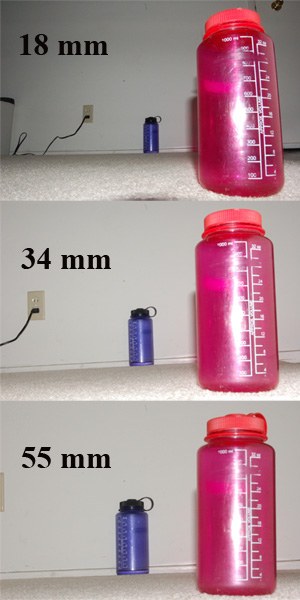
It's useful to know how different focal lengths affect the represented size of distant objects, for example:
You can also learn a lot by reading how the focal length determines the angle of view, how the focal ratio (or f-number) defines the maximum usable aperture of a lens and so on. It's really interesting.